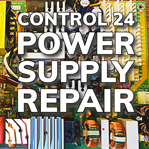
Repairing a power supply can seem daunting, but it's a valuable skill for any studio tech, especially for those working with older, unsupported equipment like the Digidesign/Focusrite Control 24 control surface. This guide will walk you through the process of diagnosing and fixing the most common issue with the Control 24: complete failure due to power supply capacitor failure.
The DigiDesign Control 24 was a staple in many Pro Tools setups as the more affordable option to the flagship ProControl. Released in March 2001, the Control 24 featured 24 motorized, touch-sensitive faders, rotary encoders, sixteen Focusrite preamps, a 5.1 capable monitor controller, and various other functionalities, making it an essential piece of equipment for many studios. Although support for this model ended in 2012, and it is no longer compatible with Pro Tools 11 and higher, many units are still in use today. The newer C|24, released in October 2007, saw its support end in December 2022, with the last compatible Pro Tools version being 2022.12.
In this blog post, we will focus specifically on the older gray Control 24. We will guide you through the steps to replace the power supply capacitors, the most common point of failure. Whether you're a DIY enthusiast or a seasoned tech professional, this guide will help you bring your Control 24 back to life.
Step-by-Step Repair Guide
Tools Needed:
- Philips screwdriver
- Soldering Iron
- Solder Sucker
- Desoldering Braid
- Solder
- Voltmeter (optional)
Parts List:
| # | Value | Voltage | Length | Diameter | Label |
| 1x | 1uf | 50v | 12mm | 5.3mm | C29 |
| 2x | 4.7uf | 50v | 12mm | 5.3mm | C20,C19 |
| 2x | 10uf | 50v | 12mm | 5.3mm | C24B,C13 |
| 2x | 33uf | 63v | 15mm | 6.5mm | C44,C38 |
| 2x | 56uf | 35v | 12mm | 6.5mm | C10,C19A |
| 1x | 82uf | 35v | 15mm | 6.5mm | C12 |
| 1x | 220uf | l0v | 15mm | 6.5mm | C24A |
| 7x | 1200uf | 16v | 28mm | 10.5mm | C25,C26,C28,C30,C40,C41,C42 |
| 3x | 2200uf | 16v | 29.5mm | 13mm | C24,C18,C29 |
| 1x | 150uf | 420v | (forgot to measure - its the big one) | C14 | |
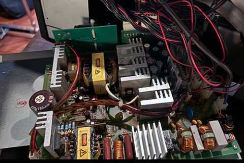
I prefer to use Nichicon electrolytic capacitors as they seem to be highest quality for me. Be sure all the capacitors you use for this repair are rated for high temperature (+105ºC) as the power supply does get quite hot. This specification will be listed on the ordering page of your favorite electronics supply company.
DigiDesign Control 24 Disassembly
Safety First: Ensure the Control 24 is unplugged from any power source. Working with electronics can be hazardous if you don't know what you're doing. Also, it's a good idea to practice on something less expensive if you are less experienced with soldering.
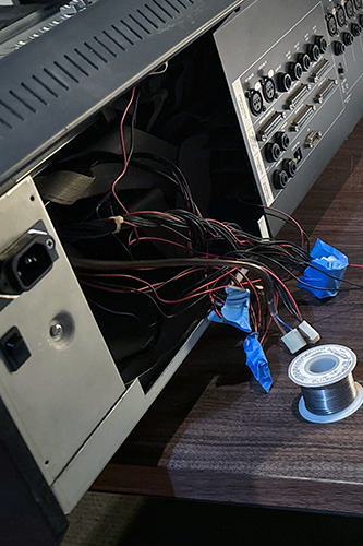
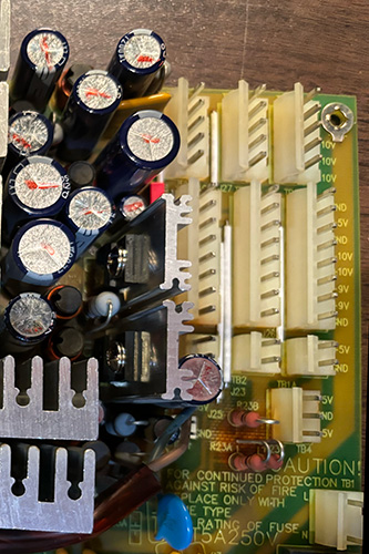
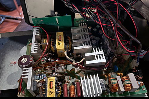
Power Supply Removal
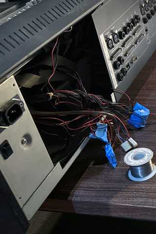
On the rear of the Control 24, locate the screws holding the power supply unit inside the chassis near the IEC power inlet. Use the Philips screwdriver to remove the screws securing the power supply. Carefully disconnect the Molex connectors to completely free the power supply from the Control 24.

Troubleshoot Power Supply
Generally, it's a good idea to make sure the power supply is the issue before continuing. Reconnect the Molex providing power, reconnect the power cable, turn the power switch on, and use a voltmeter to confirm that the power supply is not working. I hope it goes without saying that you are working with exposed electronics while the power is on... If your power supply is not working, all or some of the pins will not supply their specified voltage.

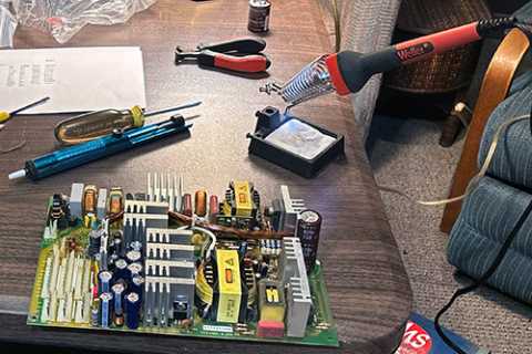
Replacing Faulty Capacitors
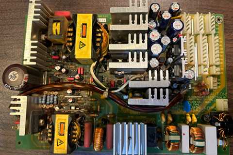
Identify the capacitors on the power supply circuit board, they look like little cylindrical cans. Use a soldering iron, solder sucker, and desoldering braid to carefully remove the old capacitors. Ensure you note the polarity of each capacitor before removal. Clean the soldering pads with a desoldering braid to remove any residual solder. Insert the new capacitors into the board, ensuring correct polarity. Solder the capacitors in place, being careful not to overheat the board.
Check Work
Inspect the solder joints to ensure they are clean and secure, with no short circuits or cold solder joints.
Partial Reassembly and Testing
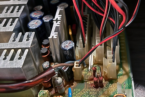
Now the hard part is done, re-connect the molex from the IEC power inlet. Carefully re-connect the power cable and power the unit on. The power supply is still out of the Control 24 chassis and exposed electronics are on your workbench! Exercise appropriate caution while testing your work and verifying your power supply repair.
The pins on the right side of the power supply are labeled with their DC voltages. Use a multimeter to verify each pin has the correct voltage. Congratulations, you've successfully completed the repair. Turn the power switch off, remove the power cable, re-connect the other molex connectors, and finish reassembly.
Testing After Repair
Initial Power-On Test
- Power on the unit and observe if the Control 24 powers up correctly.
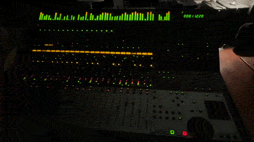
Activate Vegas Mode
- To perform additional tests, activate "Vegas Mode" by navigating through the command
Utility -> Tests -> LED -> Vegas
Common Issues and Tips
- Polarity: Ensure correct capacitor polarity by noting the direction before removal and checking the symbols on the circuit board.
- Overheating: Practice proper soldering techniques to avoid overheating the board.
- Soldering: Use an appropriate amount of solder to avoid creating short circuits.
- Physical Damage: Handle the board and connectors carefully to prevent cracking or breaking.
By following these steps, you can effectively replace the faulty capacitors in your DigiDesign Control 24 power supply, bringing your control surface back to working condition.
Conclusion
Repairing the power supply of a DigiDesign Control 24 control surface can seem like a daunting task, but with the right guidance and tools, it is a manageable and rewarding project. By following this step-by-step guide, you’ve learned how to disassemble the unit, identify and replace faulty capacitors, and reassemble the power supply to bring your Control 24 back to life.
The key to a successful repair is patience and attention to detail. Ensuring you correctly identify capacitor polarity, using proper soldering techniques, and being cautious during reassembly will help you avoid common mistakes. The use of high-quality capacitors ensures a reliable and long-lasting repair, restoring functionality to your Control 24.
Testing the unit after reassembly, including checking voltages and activating "Vegas Mode," ensures that your repair was successful and that the Control 24 is fully operational. Remember, every repair you undertake builds your skills and confidence, making you more capable of handling similar tasks in the future.