Samsung make nice monitors. They seem to look better than lots of the other choices on the shelf at the big box store where we got it and we also have an HDTV made by Samsung. So, when my computer monitor, the Samsung 2232GW started to go on the fritz, I was a little bummed. It started with a few seconds of flickering every time it turned on or woke back up. It would flicker for a few seconds and then settle down and be just fine. Eventually, the flickering lasted longer and longer and I was beginning to realize I may need to go buy a replacement monitor. I went and looked, but nothing in the selection we saw caught my eye like my current monitor. After returning home and a quick web search later, I found lots of info about capacitors, also called caps for short, going bad. You could even buy kits with the exact ones needed from several places.
I'm pretty handy with a soldering iron and know my way around Mouser.com, so I went to go take apart the monitor and see if I could see the caps that went bad. I decided to write my findings and share with everyone. It was pretty easy and I hope this info can help someone with the same issues. This issue is also common among lots of electronic devices. Manufacturers save money by putting less robust components in their products and capacitors seem prone to failure. Last year, a graphics card did a similar thing, although more catastrophically with an explosion and 'dust'? flying everywhere inside the computer!
A side note: I took these pictures and posted this how-to on my technology blog originally called DeepSeaRescue.com which is no longer up. When I took that blog down, I copied all the articles here to my site but the images still have the old blog's watermark. They are my original content as was DeepSeaRescue when it was up and running.
Disassembly Instructions
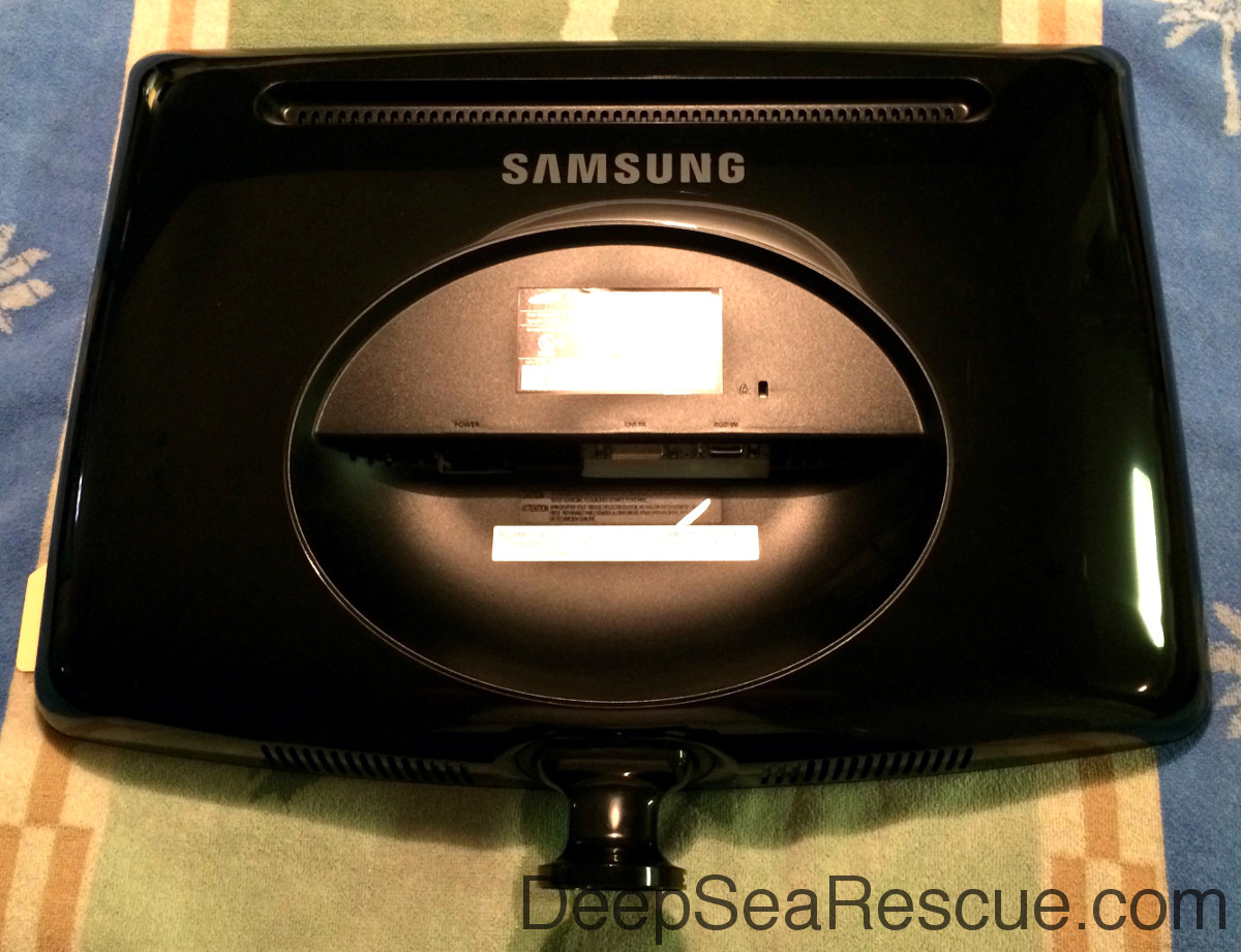
Find a work place that will not damage the screen. I used the kitchen table with a beach towel on it. Lay the monitor down and carefully pry the back off with a screw driver or other skinny flat object. There are several clips that hold the pieces together and no screws. I started at the bottom left corner and went around the top and then back to the bottom.
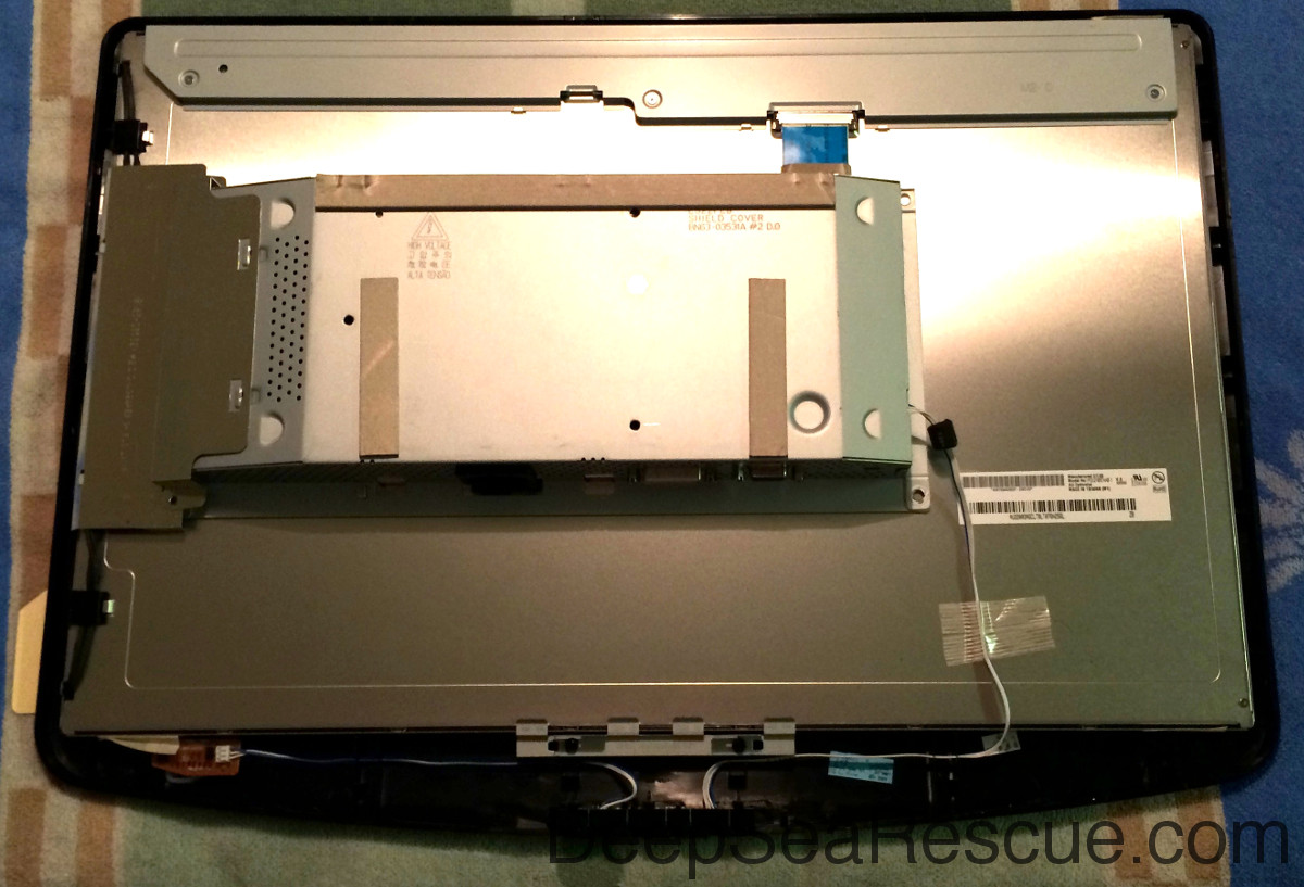
With the back off you will notice the box that holds the circuit boards. The cover on the left comes un-latches by two points.
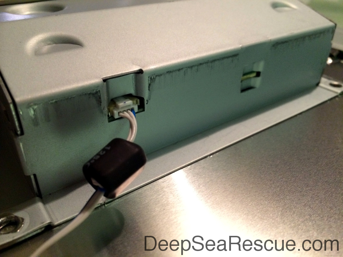
When you get that cover off, you see four sets of wires that will need disconnected. They have latches on top also. Push down of the latch and gently pull.
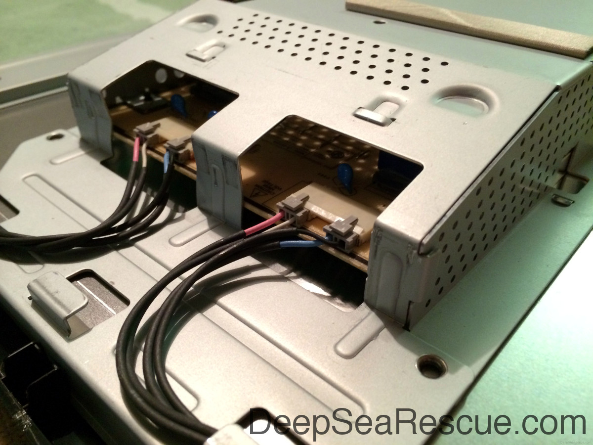
Same with the one set of wires on the other side.
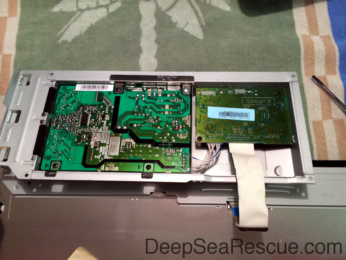
With the wires disconnected, you can rotate the box upside down to reveal the circuit boards without disconnecting the ribbon cable. I did the whole repair without disconnecting this ribbon cable. The circuit board with the bad caps on it is the one on the left in this picture.
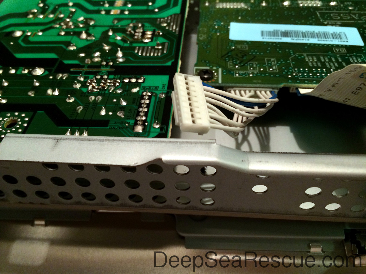
Disconnect this set of cables on the bottom left of the circuit board. There is a latch you need to press on the underside.
The board is held in place with 4 screws.
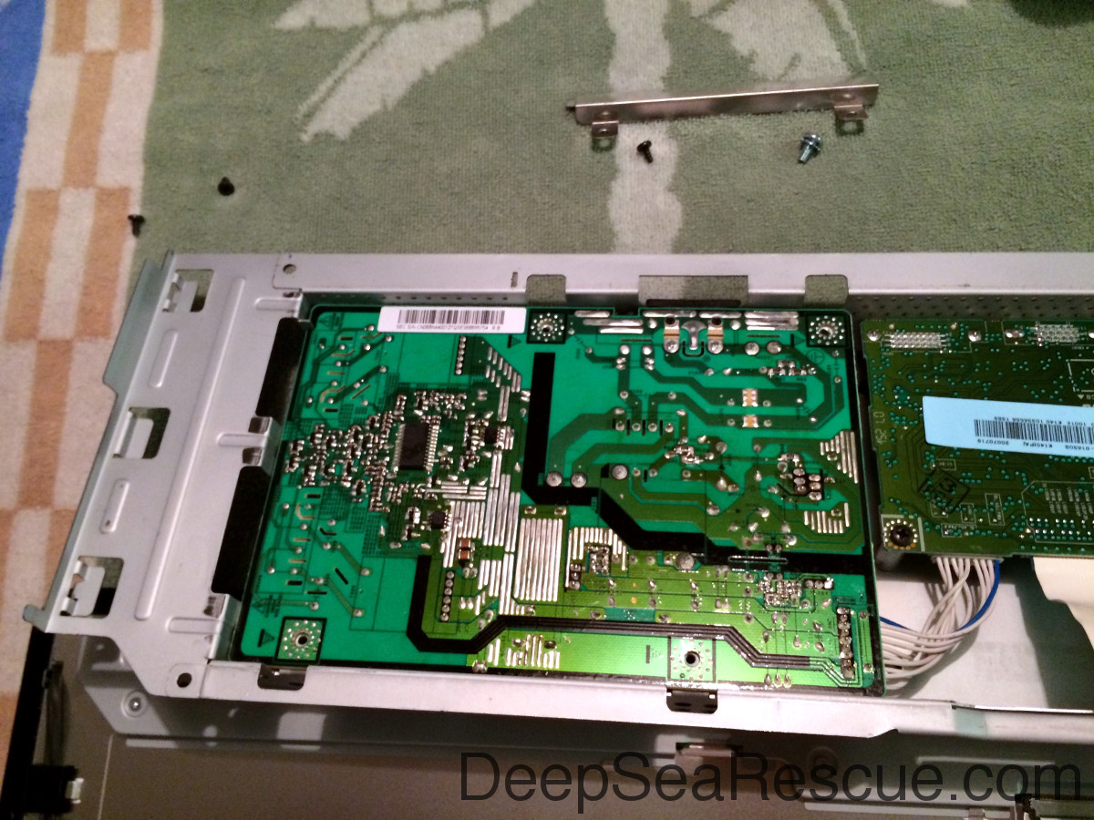
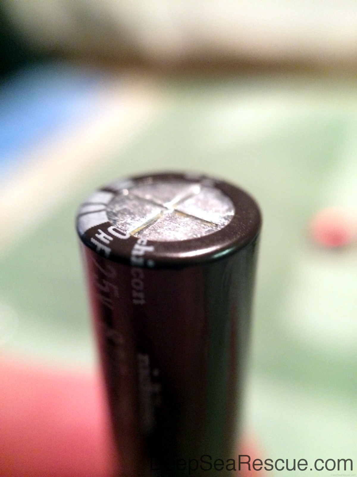
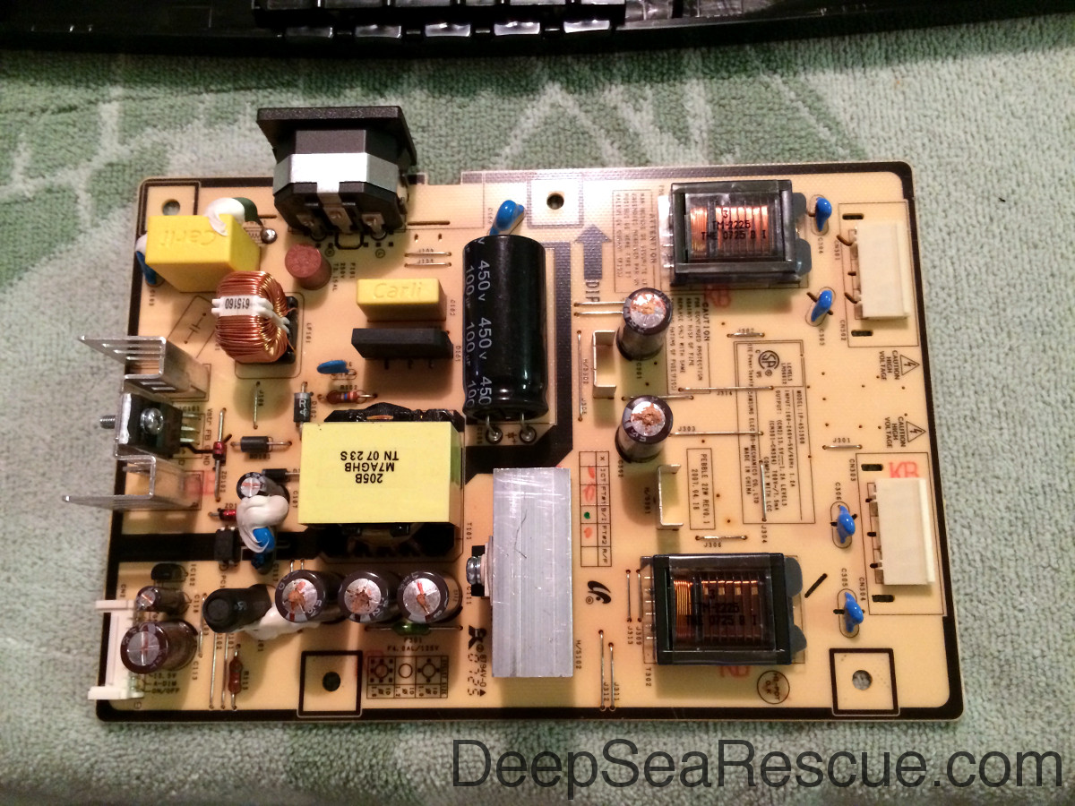
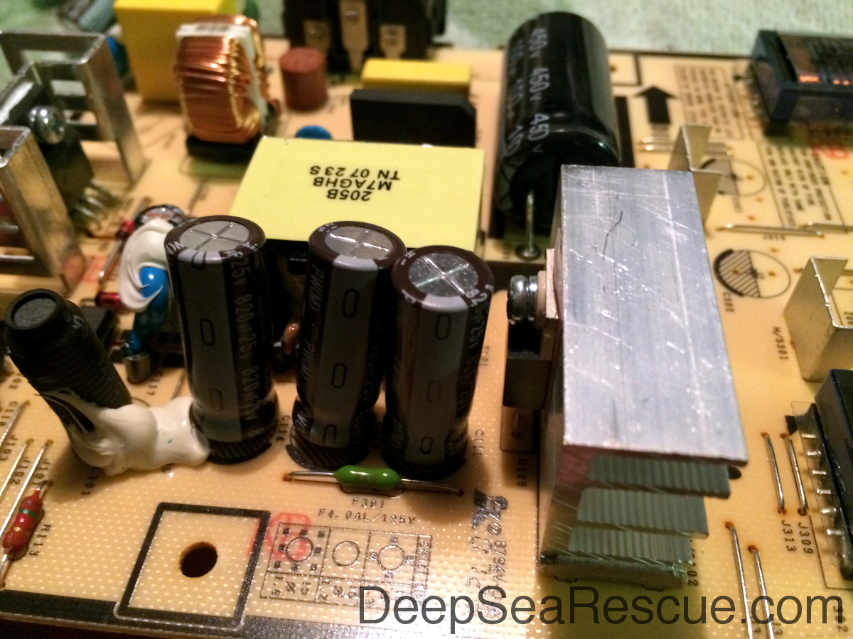
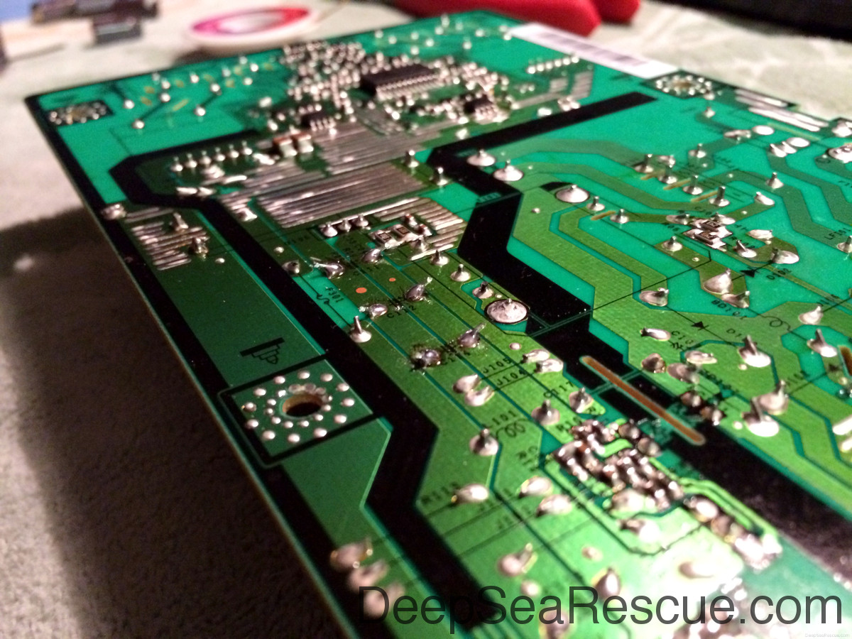
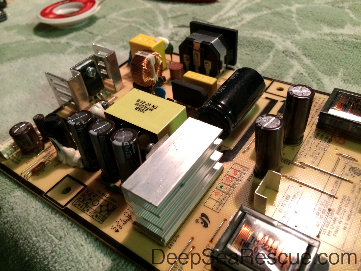
After rotating the board out, the bad caps are revealed. Some places say 7 go bad, I only had 5 identical caps go bad. Caps look like long cylindrical tubes on circuit boards. There are 5 identical ones in this pic that are showing signs of failure.
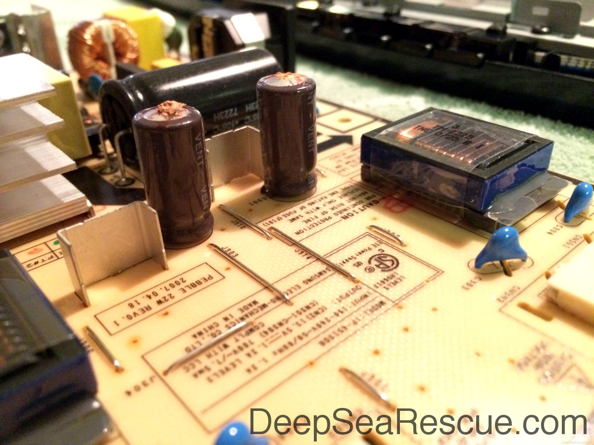
You can identify bad caps by bulging or leaking. These two are bad.
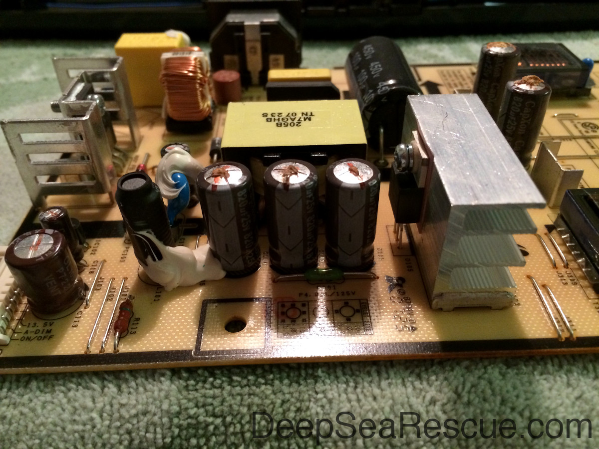
Same with these three.
Replacement Parts
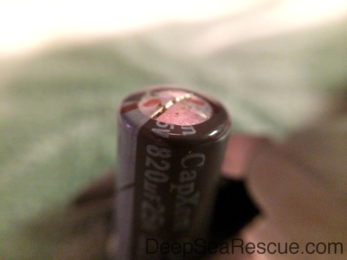
Upon inspection, they were all 25V 820µF caps. I found suitable replacements on Mouser for $0.78/ea. I ordered them and they came in two days with standard shipping.
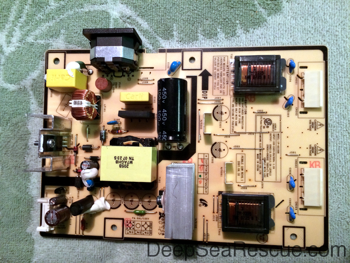
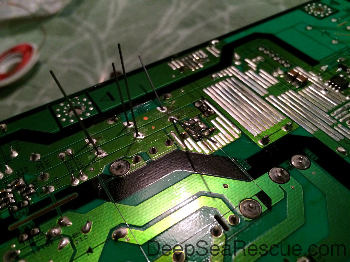
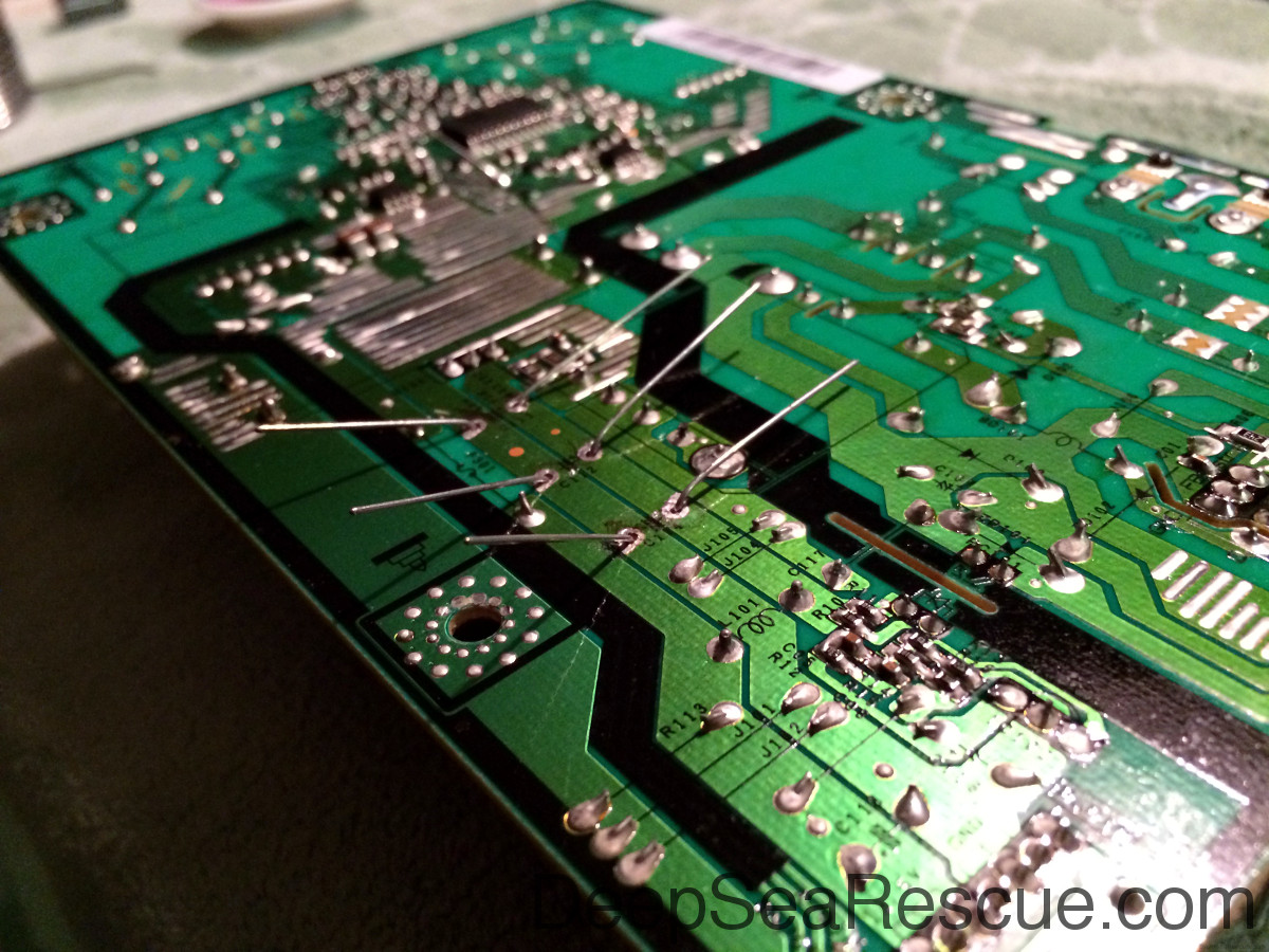
Now, remove the failed caps from the board with a soldering iron. Carefully locate the pins, there should be 2 pins, for each cap and heat them with the soldering iron while pulling or rotating the cap to pull the wire out. Do one at a time and don't over heat the board or melt anything else on the back. Bad things happen... After you get them removed, you board should look like this.
Feed the new caps through the holes. Carefully noting which side is negative, it's important for capacitors!
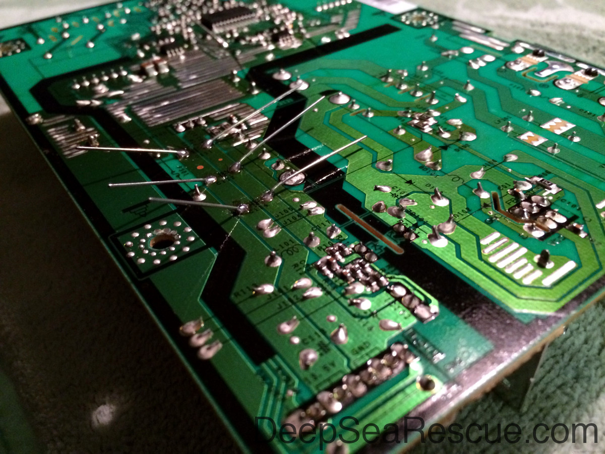
Flip it over and bend the pins out to hold them in place.
You should have them all like this.
Now, carefully solder them in. Heat the board and wire both then carefully touch your solder to them. Do not put too much solder on them, we do not want to make any other connections (shorts) to other parts.
After everything is in, you will need to clip the extra wire off.
And voila! Good as new.
Put everything back together in reverse order and test that everything is working. This project took about 30 minutes to complete.
More About Bad Caps
Identification of bad caps can be tricky. This one is only slightly bulged. It has failed and is now out of spec.
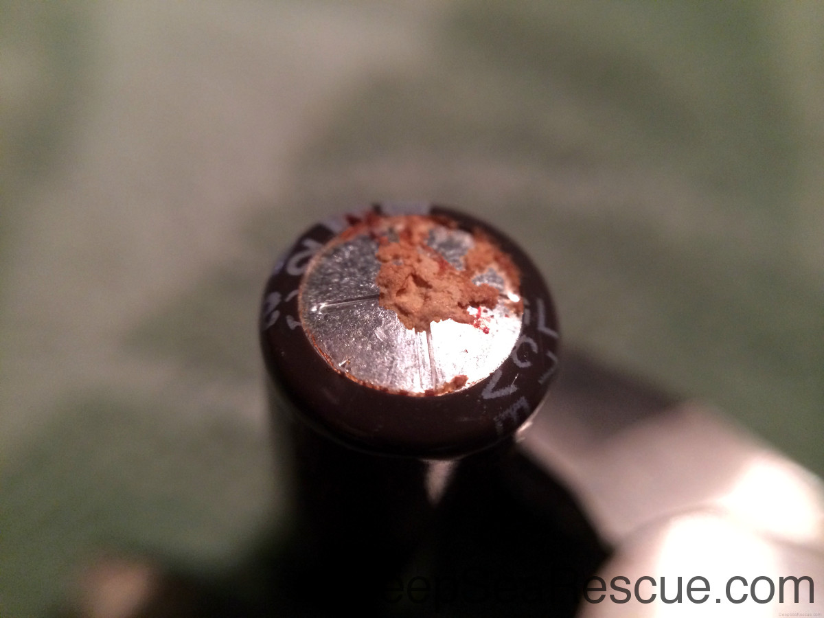
This cap is leaking and bulging. It's a lot more easily identifiable.
New caps should look like this. Flat and clean.